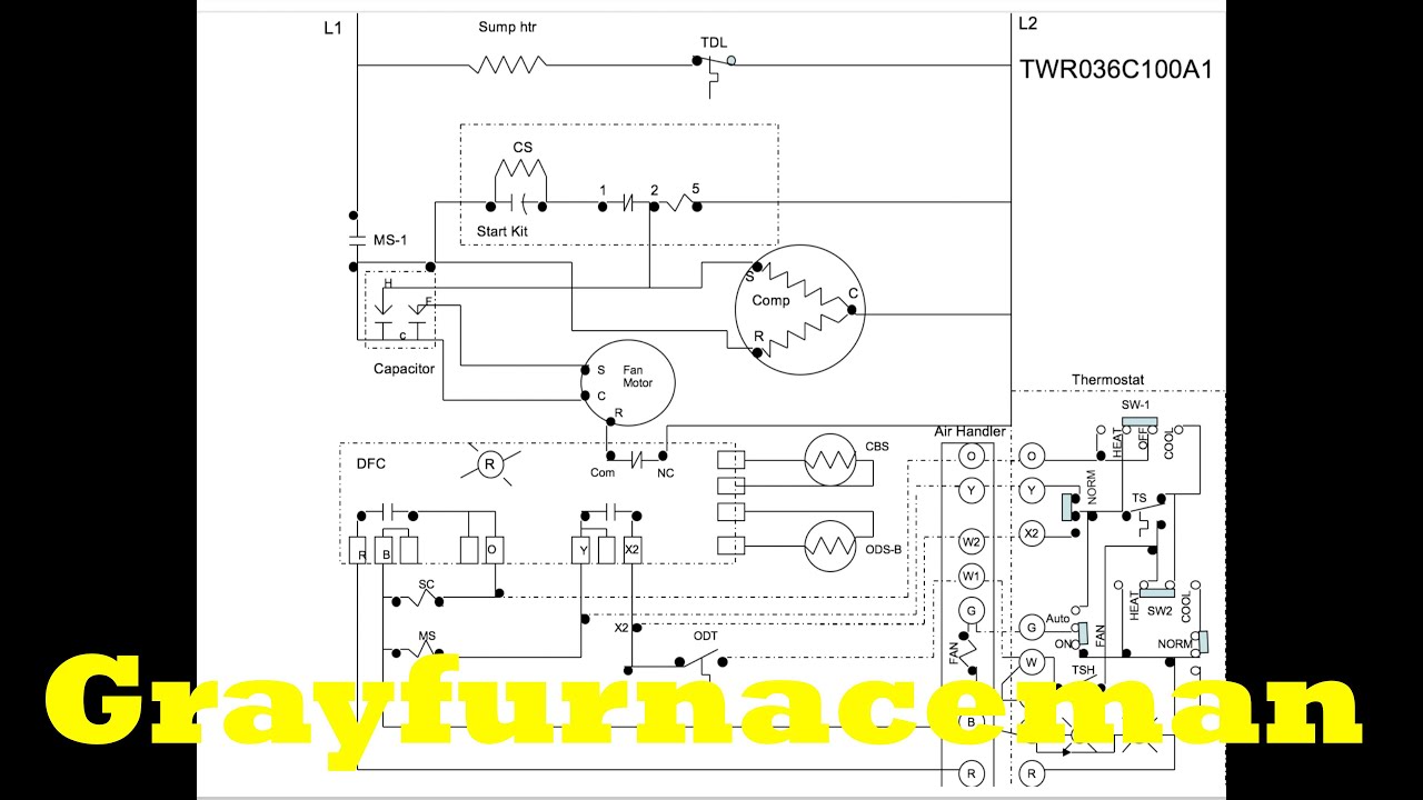
York Heat Pump Wiring Diagram. 31 b 3 h p a product nomenclature product generation 3 = third generation 4 = fourth generation product category b = single package heat pumps (air cooled) 14 this diagram is to be used as reference for the low voltage control wiring of your heating and ac system.
The heat pump wiring diagram, overview YouTube from www.youtube.com
The thermostat wire that you want to run from the air handler to the heat pump is typically going to be 1816 or 18:8 water. 1 stage heat pump 1 stage heat pump 1 stage heat pump label y1. When you employ your finger or stick to the circuit along with your eyes, it’s easy to mistrace the circuit.
Published through tops stars team in october, 6 2017.
When you employ your finger or stick to the circuit along with your eyes, it’s easy to mistrace the circuit. York wiring diagrams with rheem heat pump wiring diagram) previously mentioned will be branded having: Always follow the manufacturer’s instructions for both the thermostat and the hvac system.
If wires between the air handler and the heat pump is not.
York system wiring diagrams wd 3. I am trying to service a 17 year old york residential heat pump outside unit. The thermostat wire that you want to run from the air handler to the heat pump is typically going to be 1816 or 18:8 water.
These two connections will ensure that there is power to the thermostat that you are.
14 this diagram is to be used as reference for the low voltage control wiring of your heating and ac system. Single package air conditioners /2 thru 5 ton. With a jumper eliminating w2 out and staged electric heat.
In this wiring diagram, you will see that and you will use only 5 wires.
Ment wire must be of the type shown on the wiring diagram. York heat pump thermostat wiring diagram gallery. Rheem heat pump air handler wiring diagram, rheem heat pump low voltage wiring diagram, rheem heat pump thermostat wiring diagram,.
Getting from point a to point b.
A brief description of low voltage terminals used on york units. If wires between the air handler and the heat pump is not possible w1 and w2 can be combined at the ah. York heat pump wiring diagram gallery.
York Heat Pump Wiring Diagram. There are any York Heat Pump Wiring Diagram in here.